
ФМ предавателче
Страна 3 of 4 •  1, 2, 3, 4
 ![]()
Re: ФМ предавателче
by 50MHz-Fan Сре Окт 22, 2008 4:43 pm
[You must be registered and logged in to see this link.]
[You must be registered and logged in to see this link.]
Последната промена е направена од 50MHz-Fan на Сре Окт 22, 2008 4:51 pm. Мислењето е променето 1 пати

50MHz-Fan- Приоритетен член

- Број на мислења : 293
Registration date : 2008-07-14
Re: ФМ предавателче
by 50MHz-Fan Сре Окт 22, 2008 4:45 pm
[You must be registered and logged in to see this link.]
[You must be registered and logged in to see this link.]
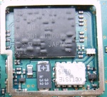
[You must be registered and logged in to see this image.]
This
FM transmitter attaches in series to one of your phone lines. When
there is a signal on the line (that is, when you pick up the handset)
the circuit will transmit the conversation. In particular it will
radiate from the phone line itself. It is a passive device - there is
no battery. It uses the signal on the phone line for power. No aerial
is needed - it feeds back the RF signal into the phone line which
radiates it in the FM band. The frequency of transmission may be
adjusted by the trimcap. L1 is 6 turns of enamelled wire, L2 is 8 turns
and L3 is 6 turns. Spread out L3 coil about 1 mm apart. The coils
should not touch. a solder connection (or tap) is required from the top
of the first turn in the L3 coil to the pad next to the coil. Solder a
piece of wire to the top of the first turn as shown on the overlay.
Then solder the other end to the pad immediately next to the L3 coil.
R1 & C4 act as a low pass filter. C3 is a high frequency shunt. L2
is a RFC (radio frequency shunt.) It decouples the power and audio from
the transmitter amplifier circuit. L1 and C6 should be adjusted to
match a frequency on your FM receiver. With C1 at 27p you will find
that the kit tunes into the FM band in the 86 - 95 MHz area. With C1 at
22p the band is raised to about 90-95mhz (depending in the coil
spacing.) If you want to move this tunable area still higher to over
100MHz range then replace C1 by a 15pF or 10pF capacitor. You can
experiment to get greater transmission range away from the phone line
by adding an aerial (about 150 cm of 26 gauge wire) to the collector of
T2.
Последната промена е направена од 50MHz-Fan на Сре Окт 22, 2008 4:50 pm. Мислењето е променето 1 пати
50MHz-Fan- Приоритетен член
- Број на мислења : 293
Registration date : 2008-07-14
Re: ФМ предавателче
by 50MHz-Fan Сре Окт 22, 2008 4:46 pm
[You must be registered and logged in to see this link.]
[You must be registered and logged in to see this image.]
The
important part of the circuit is formed of the Colpitts type
oscillator. C3,C4,C5,C6,CD1-CD2 and L1 determines the frequency. BF982
and dual gate MOSFET are active parts in oscillator. When the input
impedance of the MOSFET gate inputs are high, LC tank is not affected.
However transistors force the LC tank and cause phase shift. Two driver
stages are added to isolate the antenna from oscillator. First stage
(BF199) ampifies the low signal of the oscillator and works as a
constant load. The second stage (BFR90) amplifies the signal going
through the antenna some more. A short copper wire can be used as an
antenna here. Attaching a large antenna to this circuit is unnecessary
because the output power is low. Notes: 1. Coil 1: Winding wire must be
1 mm thick and isolated. Number of turns: 3.5 . 5mm core must be used
and the distance between each turn must be 1mm. 2. You can use BF199
instead of BFR90. 3. If you can't find the varicap diode, you can use
MV104 instead.
Последната промена е направена од 50MHz-Fan на Сре Окт 22, 2008 4:50 pm. Мислењето е променето 1 пати
50MHz-Fan- Приоритетен член
- Број на мислења : 293
Registration date : 2008-07-14
Re: ФМ предавателче
by 50MHz-Fan Сре Окт 22, 2008 4:48 pm
[You must be registered and logged in to see this link.]
[You must be registered and logged in to see this link.]
This
RF Amplifier is used for boosting small fm transmiters and bugs. It use
two Philips 2N4427 and its power is about 1Watt. At the output you can
drive any linear with BGY133 or BLY87 and so on. Its power supply has
to give 500mA current at 12 Volts. More voltage can boost the distance
but the transistors will be burned much earlier than usual.! In any
case do not exceed the 15Volts. The Amp offers 15 dB in the area of
80Mhz to 110 Mhz. L4, L5, and L6 are 5mm diameter air coils, 8 turns,
with wire 1mm wire diameter.An easy project, with great results.
50MHz-Fan- Приоритетен член
- Број на мислења : 293
Registration date : 2008-07-14
Re: ФМ предавателче
by 50MHz-Fan Сре Окт 22, 2008 4:54 pm
Encoder
[You must be registered and logged in to see this image.]
It's not important if you use this RDS
encoder with one transistor FM bug or 1 kW transmitter. It will give your station all
common RDS features: Program service name, dynamic PS, Radiotext, Program Type
identification, Traffic Program, Traffic Announcement and Music/Speech flags, Alternative
Frequencies list and some more. This unit is ideal for mounting into a small transmitter.
Modern concept is based on new [You must be registered and logged in to see this link.] chip which processes and
stores the data and generates output signal. Analogue part is very simple due to fully
digital generated RDS signal.
| Features |
- Small dimensions
- Very low power consumption
- Operates stand-alone
- Unlimited reprogramming
- Wide control possibilities
- EEPROM memory for data storage during power-off
- Broadcast quality output signal
- Continuous RDS transmission during all operations
- 4 modes for dynamic/scrolling PS incl. word alignment
and one-by-one character scrolling
| RDS services directly supported |
[You must be registered and logged in to see this image.]PS (Program Service), PI (Program
Identification), PTY (Program Type), TP (Traffic
Program), TA (Traffic Announcement), DI (Decoder
Identification), M/S (Music/speech), AF (Alternative
Frequencies), RT (Radiotext), User Defined
Groups.
(The RDS services are described in Support)
[You must be registered and logged in to see this link.] For more information download the MRDS192
datasheet.
| Technical specifications |
| Dimensions: | 4.2 x 2.7 cm |
| Supply voltage: | 7-25 V |
| Supply current: | 9 mA |
| Output RDS signal voltage: | adjustable 0-1.2 V p-p |
| RDS signal bandwidth: | +/- 2.4 kHz (43 dB) |
| Output impedance: | <400 Ohm (DC-100 kHz) |
| Communication interface: | synchronous, IIC |
| The unit layout |
[You must be registered and logged in to see this image.]
Supply - Power supply connector
1: + 7-25 V
2: ground
Check the right polarity before connecting the power supply!!!
Out - RDS output
1: output
2: ground
LPT - PC port interface
1: SDA (serial data)
2: SCL (serial clock)
3: ground
Level - Output RDS signal level
adjust
| How to connect the unit to a PC computer? |
For control purposes, the unit can be connected
either to LPT or COM port of the PC, each in unidirectional or bidirectional mode. The
control software supports all these connections.
In unidirectional mode you will not be able to read any data from the unit back to
the PC and you will not be able to detect if the data were sent successfully, but the
cable is easier to make. In standard situations any of the following diagrams will work.
- MiniRDS to LPT port connection cable
(unidirectional):
[You must be registered and logged in to see this image.]
The 680R resistor may be replaced by a diode as
in following case.
Direct connection between pins SDA and 6 is not recommended. - MiniRDS to LPT port connection cable
(bidirectional):
[You must be registered and logged in to see this image.]
[You must be registered and logged in to see this link.] - MiniRDS to COM port connection cable
(unidirectional):
[You must be registered and logged in to see this image.]
[You must be registered and logged in to see this link.] - MiniRDS to COM port connection cable
(bidirectional):
[You must be registered and logged in to see this image.]
The R9 resistor on the board should be 2k or
less in this case (default value is 4k7).
Some important notes:
- The communication interface meets the IIC serial
synchronous bus standard with the clock rate limited to 600 Hz. So the unit can be also
controlled from almost any microcontroller. - The PC control software emulates the IIC bus on a LPT
(parallel) or COM (serial) port. - You must be logged under administrator laws in
Windows to access parallel port. Serial port can be accessed in all cases. - Some low cost USB-to-COM adapters don't handle all
port pins required by the unit. You may use Port Access TEST built in the control
application to check it. - In some cases bidirectional COM connection may not
work if non-standard port is used (USB adapter, laptop PC) - use any other connection. - The RDS unit must be powered when sending any data.
- We do not supply any cables or adapters with this
unit.
As you can see, cable soldering and some basic
electronics knowledges are required. If you prefer complete plug-and-go solution rather,
look at the [You must be registered and logged in to see this link.].
| Control software for Windows |
Download: [You must be registered and logged in to see this link.]
(420 kB)
[You must be registered and logged in to see this link.]
| How to connect the unit to a transmitter? |
Answer to this question depends on the transmitter
you use:
Mono transmitter with audio or MPX input
connector (may used with stereo encoder plugged to this input)
Audio/MPX and RDS signal must be mixed together and pluged to the transmitter
input. There exist many ways to do this. You may use simple schematics provided below. The
resistor values are chosen approximately, but these values might be right.
[You must be registered and logged in to see this image.]
Mono or stereo transmitter with RDS input
connector
It's the simplest situation. Connect the encoder to this input.
Stereo transmitter with audio left and audio
right connectors and no more inputs
An encroachment to the transmitter is necassary here. Find a varicap (capacitive
diode) in oscillator and connect the RDS input connector by the following diagram. Then
fix the connector in front panel of the transmitter.
[You must be registered and logged in to see this image.]
(C) 1999-2008 Pira CZ.
All rights reserved.
50MHz-Fan- Приоритетен член
- Број на мислења : 293
Registration date : 2008-07-14
Re: ФМ предавателче
by 50MHz-Fan Сре Окт 22, 2008 4:56 pm
Kijk hoe het niet moet: Teveel ruimte tussen de windingen van de spoeltjes, en lijm gebruikt.
Aan de slag
Hierboven
zie je m'n eerste poging tot FM bug. Ik heb zorgvuldig het schema
bekeken, en alles aan elkaar geknoopt. Gelukkig is het schema niet zo
ingewikkeld, dus kon ik alles heel klein houden. Bij HF schakelingen
moet je de draadeinden zo kort mogelijk houden om zo min mogelijk
storingen te krijgen en dat is zoals je hierboven ziet goed gelukt... [You must be registered and logged in to see this image.]
Het schema voor een eenvoudige FM bug
Boodschappenlijstje
- 3 x 4.7 KOhm
- 1 x 100 KOhm
- 1 x 10 KOhm
- 1 x 270 Ohm
- 2 x 10 uF
- 1 x 1 nF
- 1 x 5.6 pF
- 1 x 2-18 pF trimmer (groen)
- 2 x luchtspoeltje 5 wikkelingen op 4 mm diameter
- 2 x BC 547 Transistor
- 1 x condensator microfoontje
Doet het niet
Helaas,
hoe ik ook aan de instelcap draaide, ik hoorde geen plop of stilte op
de radio zoals ik dat zou mogen verwachten. Dus maar eens langs gegaan
bij circuits online en de diverse forums erop nagelezen. Wat blijkt, ik
had heel die instelcap verkeerd aangesloten! Bovendien had ik de
spoeltjes niet zorgvuldig genoeg gewikkeld en die lijm die ik gebruikt
heb zou wel eens voor een load in de spoeltjes kunnen zorgen... Dus een nieuwe poging ondernomen en de instelcap losgemaakt
en opnieuw gesoldeerd, nu met de juiste aansluitingen. Bovendien had ik
nu echt gelakt 0.8mm koperdraad gebruikt om de luchtspoeltjes te
wikkelen. Maar helaas, er was nog steeds niks op de FM band te horen.
Zou ik dan toch de cap met het solderen naar z'n grootje geholpen
hebben? Tweede poging: Protobord
[You must be registered and logged in to see this image.]
Dit
is al veel beter. Versterker (links rondom beide elco's en transistor)
keurig gescheiden van HF trap (rechts rondom de instelcap en
spoeltjes), en goed gewikkelde spoeltjes van gelakt koperdraad, zonder
lijm.
Nieuwe poging
Na nog meer gelezen te
hebben over HF schakelingen besloot ik om het schema eens zorgvuldig op
een protobordje te maken. Op een bordje met eilandjes (geen baantjes,
want die pikken signaal op) plaatste ik alle componeneten zo veel
mogelijk het schema volgend. Bovendien gebruik ik voor het instellen
van de trimmer geen (metalen) schroevendraaiertje meer maar een stukje
printbord dat ik wat dunner heb geslepen. Hierdoor voorkom ik dat de
capaciteit veranderd doordat ik met een metalen schroevendraaier
contact maak met de trimmer. Hij doet het (een beetje)
Het resultaat is er
ook naar, want bij het draaien aan de cap hoor ik inderdaad een plots
hevig gekraak op de FM band. En met het instellen van de cap bepaal ik
ook nog eens waar precies tussen de 88 en de 108 MHz het gekraak
hoorbaar is. Wel verloopt de frequentie nogal sterk als ik met m'n hand
in de richting van de bug beweeg. Maar goed, het doet het dus. Alleen
hoor ik nog steeds geen geluiden die opgepikt worden door het
microfoontje. Ik vermoed dat de versterkertrap nogal sterk overstuurt.
Dus begeef ik me opnieuw op de diverse forums om eens uit te zoeken hoe
ik het ingangssignaal moet bewerken... Misschien moet ik de versterking verlagen door R2 te
verlagen van 100k naar bv 47k of 22k. Of zal ik gewoon een potmetertje
nemen? Derde poging, nieuw schema
Op de site van [You must be registered and logged in to see this link.]
kwam ik een iets andere schakeling tegen. Omdat mijn eerdere twee
pogingen niet het succes hadden dat ik ervan had verwacht besloot ik
verder te zoeken... ...wordt vervolgd...
50MHz-Fan- Приоритетен член
- Број на мислења : 293
Registration date : 2008-07-14
Re: ФМ предавателче
by 50MHz-Fan Сре Окт 22, 2008 4:57 pm
HIGH POWER FM MIC
by Harry Lythall - SM0VPO
[You must be registered and logged in to see this image.]
My FM Wireless Microphone has been a very popular project with
beginners and experienced constructors alike. It has been used
inside guitars and as the basis of a remote control system. I
do however, receive many requests for a higher powered circuit
and better microphone sensitivity. Now I can introduce the new
FM Wireless Microphone (v5), which also has a better frequency
stability, over 1Km range (under ideal conditions) and is good
on microphone sensitivity. This has been achieved by adding an
RF amplifier buffer (with 10dB gain) and an AF preamplifier to
boost the modulation a little.
[You must be registered and logged in to see this image.]
Construction is quite simple. L1 is 3.25 turns in spiral form
and is an integral part of the PCB foil pattern. The two BC547
transistors can be replaced with (almost) any small-signal NPN
transistor, such as the 2N2222. The final stage is a BC557 PNP
general purpose device. If you use different devices then you
should select the 1M0 resistor for 5-volts DC at the collector
of the the first transistor. Select the 47K resistor for 3 - 4
volts on the collector of the third transistor. Here is the V5
component overlay drawing. Note that there is a modification:
[You must be registered and logged in to see this image.]
There used to be a 1n0 5mm cap for supply decoupling, but after
a cange of component supplier (manufacturer?) there developed
some form of RF instability when the gain of the PA transistor
was a little above normal. Replacing the 1n0 to an electrolytic
capacitor of 22uf cured this problem totally. Any "radial" (the
leads both come out of the same end) type electrolytic capacitor
from 0.47uf upwards cures the problem. The finished unit draws
about 30mA which should vary as you touch the tuned circuit, a
good test that the unit is oscillating. You should remove the
4K7 resistor if you use a dynamic microphone.
[You must be registered and logged in to see this image.]
The PCB is 50mm x 25mm, a little larger than the first version
but there are three stages instead of just the one. The first
prototype is shown above, beside the battery powering it. The
output power is about +10dBm which is about 10dB more than the
first FM Wireless Microphone. This would theoretically give it
3.12 times the range (1.6Km) but I have only tested it using a
handheld receiver with the TX laying on the bench indoors. But
I got a comfortable 700 meters (and a few funny looks from our
neighbours).
[You must be registered and logged in to see this image.]
Above you can see the addition of a "gimmick" capacitor added
across the 12p tuning capacitor to lower the frequency of the
transmitter. Make the capacitor by twisting two lengths of
single core insulated hook-up wire, about 2cm long. This will
reduce the frequency to the bottom end of the band. Cut short
the capacitor to increase the frequency to the desired final
frequency. If you cut it a few KHz too high then just twist
the gimmick a little tighter.
The PCB foil pattern and layout will be placed in the download
section of my homepages. Have fun and please be aware that the
higher power of this project may render it ILLEGAL in your own
country. I can accept no responsibility and it is up to you to
check that you may legally use it. I will accept NO complaints
from any country/state correctional facility.
Very best regards from Harry Lythall
[You must be registered and logged in to see this image.]
[You must be registered and logged in to see this link.]
50MHz-Fan- Приоритетен член
- Број на мислења : 293
Registration date : 2008-07-14
Re: ФМ предавателче
by 50MHz-Fan Сре Окт 22, 2008 5:02 pm
[You must be registered and logged in to see this link.]
[You must be registered and logged in to see this link.]
50MHz-Fan- Приоритетен член
- Број на мислења : 293
Registration date : 2008-07-14
Re: ФМ предавателче
by Dimce Чет Окт 23, 2008 5:21 pm
Dimce- Радиоаматер
-
 Број на мислења : 71
Age : 44
град : Strumica
Хоби : Elektronika
Омилен банд : FM
Registration date : 2008-09-21 -

Re: ФМ предавателче
by Niki Пет Окт 24, 2008 9:31 am
интернет не е проверено.

Niki- Професор

- Број на мислења : 1717
Registration date : 2008-05-05
Re: ФМ предавателче
by Dimce Пон Окт 27, 2008 3:18 pm
Последната промена е направена од Dimce на Пон Окт 27, 2008 3:28 pm. Мислењето е променето 1 пати
Dimce- Радиоаматер
- Број на мислења : 71
Age : 44
град : Strumica
Хоби : Elektronika
Омилен банд : FM
Registration date : 2008-09-21 -
Re: ФМ предавателче
by Dimce Пон Окт 27, 2008 3:27 pm
Dimce- Радиоаматер
- Број на мислења : 71
Age : 44
град : Strumica
Хоби : Elektronika
Омилен банд : FM
Registration date : 2008-09-21 -
Niki- Професор
- Број на мислења : 1717
Registration date : 2008-05-05
Re: ФМ предавателче
by Dimce Чет Окт 30, 2008 4:49 pm
Dimce- Радиоаматер
- Број на мислења : 71
Age : 44
град : Strumica
Хоби : Elektronika
Омилен банд : FM
Registration date : 2008-09-21 -
Re: ФМ предавателче
by Niki Пет Окт 31, 2008 8:16 am
А оваа добра е?50MHz-Fan напиша:
[You must be registered and logged in to see this link.]
[You must be registered and logged in to see this link.]
Niki- Професор
- Број на мислења : 1717
Registration date : 2008-05-05
Re: ФМ предавателче
by Dimce Пет Окт 31, 2008 4:37 pm
Последната промена е направена од Dimce на Чет Ное 06, 2008 6:08 am. Мислењето е променето 1 пати
Dimce- Радиоаматер
- Број на мислења : 71
Age : 44
град : Strumica
Хоби : Elektronika
Омилен банд : FM
Registration date : 2008-09-21 -
Re: ФМ предавателче
by SW Пон Ное 03, 2008 1:36 pm
SW- Редовен форумџија

- Број на мислења : 158
Age : 35
град : skopje
Хоби : Radio Amaterizam
Омилен банд : SW
Registration date : 2008-08-24 -
Re: ФМ предавателче
by Dimce Чет Ное 06, 2008 6:07 am
Dimce- Радиоаматер
- Број на мислења : 71
Age : 44
град : Strumica
Хоби : Elektronika
Омилен банд : FM
Registration date : 2008-09-21 -
Re: ФМ предавателче
by Dimce Саб Ное 08, 2008 5:28 pm
Dimce- Радиоаматер
- Број на мислења : 71
Age : 44
град : Strumica
Хоби : Elektronika
Омилен банд : FM
Registration date : 2008-09-21 -
Re: ФМ предавателче
by Dimce Чет Ное 13, 2008 7:01 am
Dimce- Радиоаматер
- Број на мислења : 71
Age : 44
град : Strumica
Хоби : Elektronika
Омилен банд : FM
Registration date : 2008-09-21 -
Georgi- Професор
- Број на мислења : 1058
Age : 34
град : Троян
Хоби : Satellite DXing
Омилен банд : Ku/C-Band
Registration date : 2008-05-05 -
Niki- Професор
- Број на мислења : 1717
Registration date : 2008-05-05
Re: ФМ предавателче
by Dimce Чет Ное 13, 2008 7:58 am
Dimce- Радиоаматер
- Број на мислења : 71
Age : 44
град : Strumica
Хоби : Elektronika
Омилен банд : FM
Registration date : 2008-09-21 -
Re: ФМ предавателче
by Dimce Сре Ное 19, 2008 4:15 pm
Dimce- Радиоаматер
- Број на мислења : 71
Age : 44
град : Strumica
Хоби : Elektronika
Омилен банд : FM
Registration date : 2008-09-21 -
Re: ФМ предавателче
by Dimce Пет Дек 19, 2008 11:06 am
Dimce- Радиоаматер
- Број на мислења : 71
Age : 44
град : Strumica
Хоби : Elektronika
Омилен банд : FM
Registration date : 2008-09-21 -
Страна 3 of 4 • 1, 2, 3, 4 ![]()
|
|
|